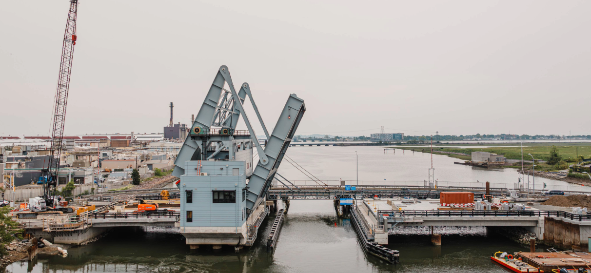
On the coast of Massachusetts, north of Boston, the design of the Belden Bly Bascule Bridge, which connects Lynn and Saugus, presented an intricate puzzle for our team at STV – one that tested our creativity, technical acumen and commitment to community needs.
The Belden Bly Bridge replaces an aging rolling lift bascule bridge that had reached the end of its useful life. On behalf of the Massachusetts Department of Transportation (MassDOT), STV served as lead designer for this replacement program. Our primary goal was to create a bridge that would seamlessly integrate into the existing landscape while providing an efficient and safe passage for both vehicles and marine vessels. With the Saugus River being a local fishing and pleasure craft hub, the design also had to account for significant marine traffic – opening approximately 2,500 times each year.
During a recent presentation at the International Bridge Conference, our team highlighted the series of challenges we faced in delivering this project: limited clearance over the river, the need to limit excavation at the site, the need to provide a movable bridge configuration that ensures operational resiliency and a mandate to incorporate bike lanes and sidewalks, resulting in unusual span geometrics. In each instance, we approached these challenges as an opportunity to innovate and enhance the bridge’s role as a vital connector within the community.
Engineering a First-of-Its-Kind Movable Span
A pivotal technical hurdle was the configuration of the bridge superstructure, which is crucial for the operation of any movable bridge. Given the low level of the roadway, the requirement to limit excavation and the tidal nature of the Saugus River, eliminated the potential for a deep closed pit bascule pier foundation to accommodate a traditional simple trunnion bascule bridge. Similarly, the low clearance over the river, compounded by the surrounding roadways and properties, limited our options for accommodating any significant increase in the roadway elevation.
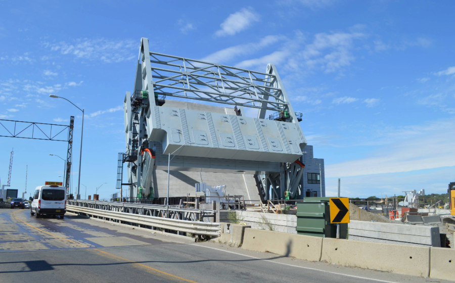
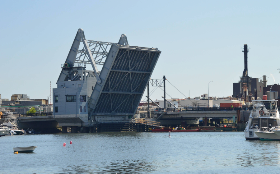
The owner was not inclined to replace the existing bridge with a new rolling lift span due to the numerous problems the old bridge exhibited. The options that would limit excavation, provide resiliency and accommodate the tight geometrics of the site resulted in a design classified as a heel trunnion bascule bridge with an overhead counterweight – an innovative solution that allowed us to meet all the project requirements. In addition, this approach offered several other advantages, including minimizing the right-of-way impacts on the neighboring properties and improving the overall streetscape with the ADA additions. However, it also introduced complexities in the overall design, specifically for the system of linkages and overhead counterweight arm and a unique span drive machinery configuration that utilized a large segmental gear instead of the historically standard overhead articulated rack.
From an operational perspective, a heel trunnion bascule bridge differs from a conventional trunnion bascule because the counterweight is essentially cut off the back of the bascule girder, and placed up above the roadway level through an assembly of raised girders and linkages Positioned above the roadway, the counterweight is supported by multi-directional framed towers, which was also used to support the main span drive machinery which we then placed in a structural enclosure. The heel trunnion counterweight system is a complex design challenge that demands attention to detail, best practices for addressing fatigue-prone and non-redundant elements (common in movable bridge design), a much more intricate span balance analysis and must make allowance for large span drive machinery equipment and accommodate a very sophisticated state-of-the-art electrical drive and control. And overshadowing all the above demands, no movable bridge type (a bascule compared with a lift bridge or swing bridge) requires more attention to ensuring that all the moving parts have sufficient clearance to accommodate temperature variations, wind and other external loads throughout the entire range of travel. We also took extreme precautions to accommodate the highly unlikely case of a runaway span and upper counterweight arm striking the supporting towers. In short, a challenging assignment.
Balancing Machinery and Aesthetics
Our interdisciplinary structural, mechanical and electrical teams embraced a collaborative, holistic approach, working closely to address the bridge’s unique challenges. The process starts by training the different disciplines to respect and understand the demands of others. Throughout the design process, we explored configurations that best accommodate the necessary machinery within the developing structural configuration. Using CAD-based technology, we could assess clearances and potential fouling through detailed simulations running the span through its full range of travel.
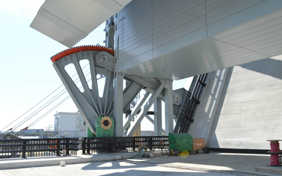
By integrating the machinery room within the tower, we provided robust support while keeping the structure’s aesthetics as clean as possible. The span drive machinery utilized a unique approach to raising and lowering the span. Historically, the span drive for a movable bridge like this one would start with a high-speed electric motor driving a series of either open or enclosed reduction gears, so speed is reduced while drive torque is increased until we get to the main pinion that drives an articulated rack connected to the bascule girder. Because of the adjacent sidewalks and potential for injury, as well as resulting gear lubrication spilling onto the sidewalks, we decided we would drive the span through a large segmental gear connected to the span through a link arm, which ultimately provides for the raising and lowering of the span.
Most movable bridge machinery assumes that the span is balanced throughout all travel positions. The center of gravity of the moving parts must stay in proper alignment as the span raises and lowers. To maintain a fully balanced operation. All the primary span drive and span support linages must form a parallelogram throughout travel. One of the more challenging aspects of the construction is assessing that the members will form this parallelogram while still in the shop, before all the dead load is placed and the bridge takes its final geometry. Our plan set guided the fabricator on how to check the dimensions of the linkages and confirm the parallelogram in the ‘no load’ condition on the shop floor. Another innovative presentation in the plans.
Supporting Complete Streets and Community Needs
Massachusetts adopted a complete streets initiative during the design phase, which presented additional requirements. The increased need for bike lanes and sidewalks increased the overall width and weight of the movable span, leading to unusual span geometries. This meant we had to incorporate these elements without compromising the bridge’s functionality, further complicating our design process. As part of the design, we explored several lightweight concrete deck filler materials and utilized an optimized girder-floorbeam-stringer framing system incorporated into the plans.
The design of the Belden Bly Bascule Bridge illustrates the power of thoughtful collaborative engineering. By carefully navigating the technical challenges – from selecting a heel-trunnion configuration to accommodating required community needs – our team at STV created a bridge that serves as a vital connector for the region while supporting local economic and recreational activities for decades to come.
It is a testament to what can be achieved when teams come together with a shared vision of innovation, safety and community enhancement. The Belden Bly Bridge stands as a proud example of our commitment to overcoming engineering challenges and reinforcing the essential role of infrastructure in enhancing the quality of life for communities across Massachusetts.